Sending your design to a bureau

Sending your design to a print bureau

If you’re planning to use a bureau to print your design, you could just send over your CAD model in a neutral file format like STEP, 3MF or STL. However, when translating your file to the actual gcode that will drive the 3d printer, the bureau will choose the values of different variables that will affect the final part properties, so we recommend you try and specify as many of those as you can. There are also post-processing steps to consider that will affect your final part quality. Specifying what you require at each step will help you get as close as possible to your expected result.
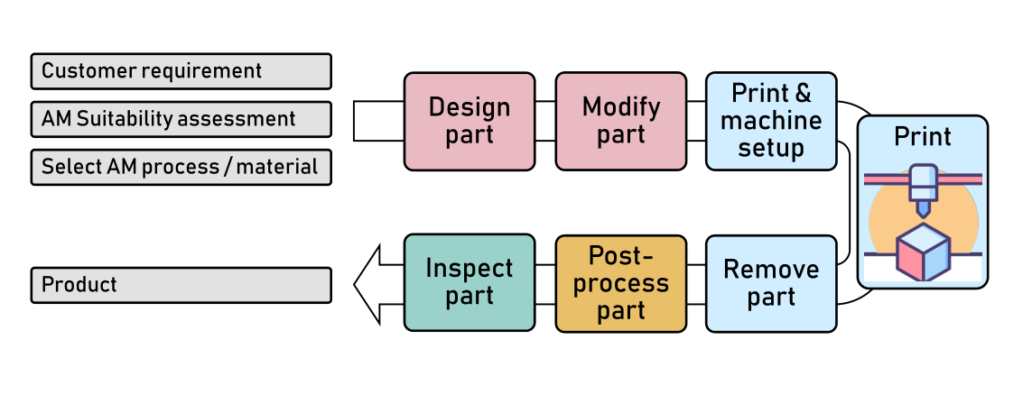
3DP workflow (MakeAmaze)

For a MEX part, these are parameters to consider specifying when you upload your CAD model:

Stage

Variable

What it affects in the final part

How to define it

Build layout

Orientation

Amount of support material, surface texturemechanical properties (see BP033).

Note that this also affects build time and therefore, cost.

Send instructions to use the part’s orientation as supplied

Supports

Where to permit supports, what type (tree etc).

Send a 3MF file that includes your part and the supports as separate items

Slicing

Nozzle diameter

Resolution of sharp corners, wall thickness (number of passes needed), minimum/maximum layer height. A bureau may favour a large nozzle for speed, but you may a small nozzle for definition.

Indicate the minimum feature resolution you need and the required tolerance, to ensure the correct nozzle size is used.. Bear in mind that loaded filaments such as wood, CF or GF filament may require a large nozzle, e.g. 0.8mm

Layer thickness

Vertical resolution (stepping), surface texture.

Note that this also affects build time and therefore, cost.

Request a specific layer thickness

Wall thickness

Part strength

Note that this also affects build time and therefore, cost.

Specify a minimum number of inner shells

Infill

Part strength

Note that this also affects build time and therefore, cost.

Specify the infill percent (and pattern if you know the slicer that will be used) or indicate that the part needs to be mechanically strong.


If the bureau agrees, you could even use your own slicer to create a gcode file and send that, for the bureau to use as a reference.

Post-processing

Support removal

You may want the part shipped with supports attached.

Indicate if you want supports removed or you prefer to do it yourself

Heat treatment

Thermally treating some materials (eg PLA) can improve their mechanical properties.

If the bureau does provide this service, there should be a number of standard treatments to choose from. Otherwise it may need to be done inhouse.

Vapour smoothing

Vapour smoothing improves texture and even water tightness of the part, but can adversely affect the mechanical properties if not done correctly. More information here

If the bureau offers this process, then you should first discuss the expected loss of detail/ dimensional changes to the part.

Plating/coating

Plating or coating can change the appearance and function of the part, for example electroplating would make the part electrically conductive

These are normally specialist services not offered directly by a print bureau. You should discuss your requirements directly with the service provider.

For a list of what else to check before sending your file, such as making sure the scale of your model is correct, Shapeways have a good guide here.

What is Quality in AM design?

What is Quality in AM design?

One aspect of Quality in DfAM is the value it adds. Just because AM allows ‘design freedom’ doesn’t mean any design is ok! And in fact with AM, not designing things right can get expensive very quickly. In addition, AM has some real weaknesses when challenging conventional manufacturing, e.g. Injection Moulding (IM). The texture, the sheen, the colour, the materials, the perfection of conventionally manufactured objects, the consistency of form and of material structure across all feature sizes. These are things that AM can’t beat. A design for AM needs to add value to make sense. Then it can compete with conventional manufacturing processes and even be better.

So by a design that incorporates ‘value’ we mean one that makes things better than they were before that design existed. In the majority of cases that means something that is designed to the strengths of AM and away from its weaknesses, that encompasses a benefit and that is designed to be manufactured with the lowest ‘cost’. ‘Cost’ includes manufacturing risk and manufacturing time as well as overall piece price.

By ‘manufacture’ we mean everything that needs to be done to that part to give it to a user, and that is not just ‘printing’ it. A quality part design should leave your workstation and go to the shop floor with all the accompanying information for people who will receive and manufacture your design, from build preparation, support placement, post-processing, inspection.

The data for the downstream process steps will comprise:

  • A model of the net shape part (usually a CAD model).

    • Depending on the company processes this could be the native CAD model but is usually a file format that the slicer can process. Some slicers process STEP files but most need a tessellated file. STL is a legacy file format that is prone to errors and doesn’t carry metadata. So we would recommend (provided downstream process steps accept it) that you use 3MF since it can carry additional information about supports, build file orientation , lattices etc.

  • Accompanying information that build preparation and manufacturing need. This will include:

    • Build setup variables

    • Post-processing and inspection requirements (described in the SkillsMove nuggets) as per conventional manufacturing Product Modelling Information (PMI)

So if you put those things together, a Quality design is the right application, with the right choice of process and the right material, the right geometry and the right instructions to people downstream in the process chain, such that the experience for everyone involved is seamless. That seamlessness is dependant on the choices embedded in the design by the designer. Such a design will be adding value, and minimizing the downside / risks of AM.

In the case of prototyping, where the aim is just get fast iterations in your hand, to see what the design concepts look like in reality, or when you a further along the design process, to check form, fit and function, then the requirements for a quality design don’t really apply. It’s all about playing in a sandbox, using a printer to help evaluate your ideas and then discarding them and moving on.

It’s worth saying that good AM design isn’t defined by complexity. A simple bracket that replaces a conventionally manufactured one can be a good quality design. It adds value if its function or aesthetic is improved, or it’s opened new markets for the seller of the bracket, or it’s made manufacturing faster or cheaper, less dependant on the supply chain, or has a lower environmental impact, or any combination of the above. If that is coupled with an absence of design-induced manufacturing risk, or difficulty in post-processing & inspection, then we would call that a quality AM design.

So in summary, a quality AM design:

  • Adds value through use of AM instead of conventional manufacturing

  • Minimises manufacturing cost and risk along the whole AM process chain i.e. print file preparation, printing, post-processing and inspection

  • Is a file of the part geometry accompanied by complete and unambiguous information that the downstream process steps will need


Reversible or non-reversible AM

How much commitment does AM need?

1. Introduction

As a company is deciding whether to implement AM for parts and assemblies, the question of risk is intrinsic to the decisions they will take. The product requirements you receive as a designer will reflect the company’s attitude to risk and it is worth having the big picture in mind for your discussions with your internal or external customers. 

1.1.Make prototypes 

The easiest and safest way to try using AM is to make prototypes. Here the risk is essentially zero and the benefit is speeding up the design process, by rapidly iterating through design solutions, using physical prototypes to test form, fit and even function. 

The next step would be to use AM for a functional part. A common example of this is the use of AM for jigs and fixtures. The jigs and fixtures can be tailored to individual operators or parts and can be low cost. If they have a short working life or don’t work perfectly, then there is little loss. In this case as a designer you have full freedom to do DfAM from first principles, exploring the freedom of AM and design almost by trial and error to reach a solution that works. 

1.2.Use AM to make existing parts 

A company that is willing to increase their risk can try using AM for end-use parts. Here, things are more serious because material properties matter, product life is important and there may be certification or other regulatory considerations. A company could approach this incrementally, first by substituting an existing part they make with one made by AM. They will need to achieve the same fit and function and there will be restrictions on form. The part will have to fit into the same volume the original part occupied. It will most likely be made of the same material (or an AM equivalent) as the original part. Here, design may well be a case of modifying the existing design to make it manufacturable by AM, i.e. a DfM exercise, without thinking about design freedoms. Some people refer to this as Modification for Manufacture (MfM) i.e. it’s a precursor to doing full DfAM. The commitment by the company in this instance is “reversible” in the sense that, if the AM part doesn’t work or the production quality is poor or there are supply chain issues etc, then the company can easily switch back to using the original part. 

1.3.Improve parts 

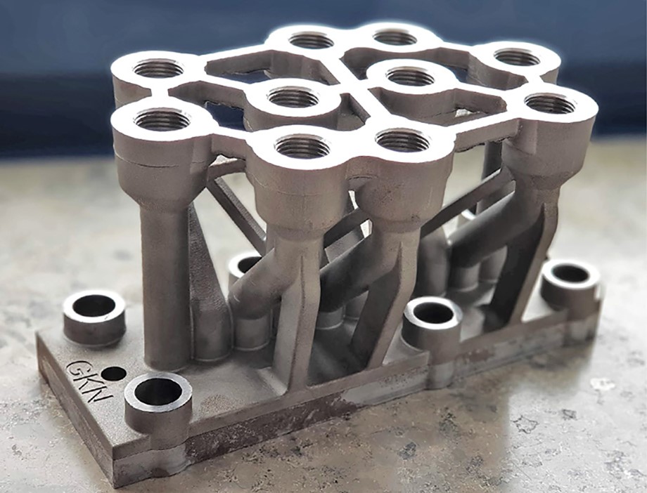
Another example is fluidic manifolds,  such as the one shown below. In this case, as a designer you can use AM for the benefit reducing material mass and material waste (if machining) to make an AM version of the manifold, while respecting the interface points of the manifold in the overall system. This way, the original manifold can be used if needed. This is reversible commitment. 

1.4. Change the interfaces 

The next step may be to make the manifold smaller and even lighter by optimising the paths the fluid flows along. The new manifold will have different interface points, meaning that the connectin g pipework will change. This is ‘irreversible’ commitment in the sense that the original cant just be switched back in. 

An AM manifold block that maintains the same interface points as the conventional one (GKN )

1.5.Design AM-only parts 

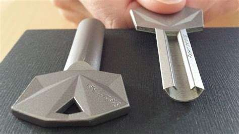
Companies with sufficient confidence in AM can take the step of developing a new part that can only be made use AM. An example of this would be the stealth key as shown in the image below. It has the key teeth on the internal face of the key. It has been designed taking full advantage of AM ‘design freedoms’. Here the risk is that somewhere along the process chain a problem emerges (for example supply chain issues, quality control, verification testing etc). In this case, the company would lose the product due to their dependance on AM as the manufacturing route. 

http://www.kleidamparosou.gr/home/111-urban-alps-stealth-key.html

A key that is only practically manufacturable using AM (Urban Alps )

1.6.Build systems containing AM parts 

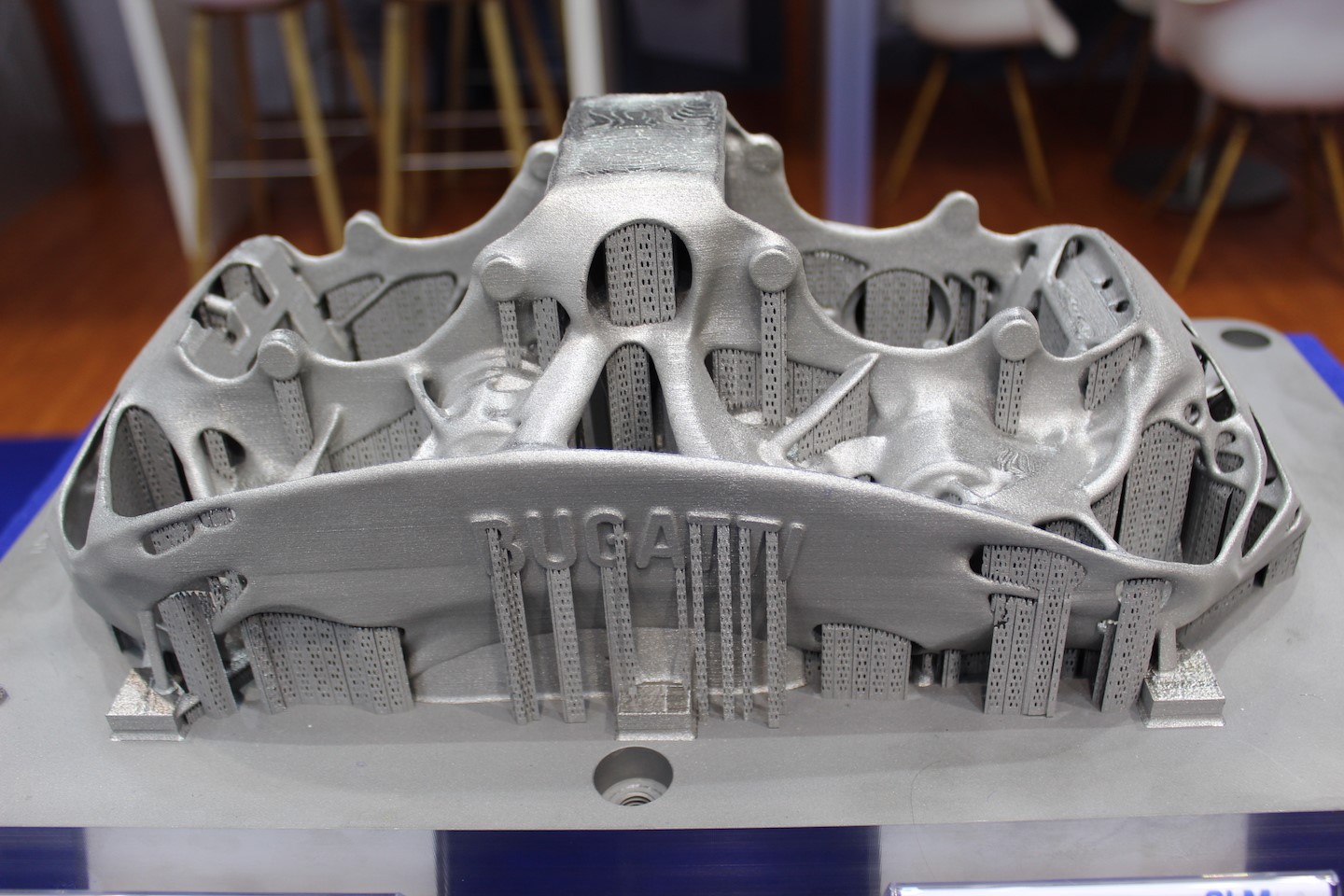
A step beyond this is to create mechanical or other systems that rely on one or more AM parts. Here the interaction of parts in the system, their material properties, mass, packing space are all entangled. A good example is the AM brake caliper used by Bugatti. Replacing the caliper with a conventional one that needs a larger volume or is heaver, will mean that interface points will move, other parts will have to be redesigned and this will impact the dynamic behaviour of the whole wheel assembly.  

An AM brake caliper (Bugatti)

1.7.Functional consolidation of parts 

And finally, the ultimate expression of commitment to AM is to design components that combine the functionality of many parts into one. For example take a rocket nozzle that has internal cooling channels integrated into the nozzle. It has dual function ( exhaust jet forming and cooling). Here the functions and forms are intrinsically bound together and you are fully commited to AM. As a DfAM designer this may be the most fulfilling type of design you will be asked to do! 

RAMFIRE Aerospike nozzle (NASA)

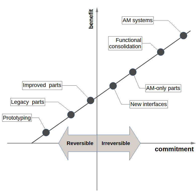
The image below represents this concept graphically

Commitment to, and Benefit from, AM (MakeAmaze)